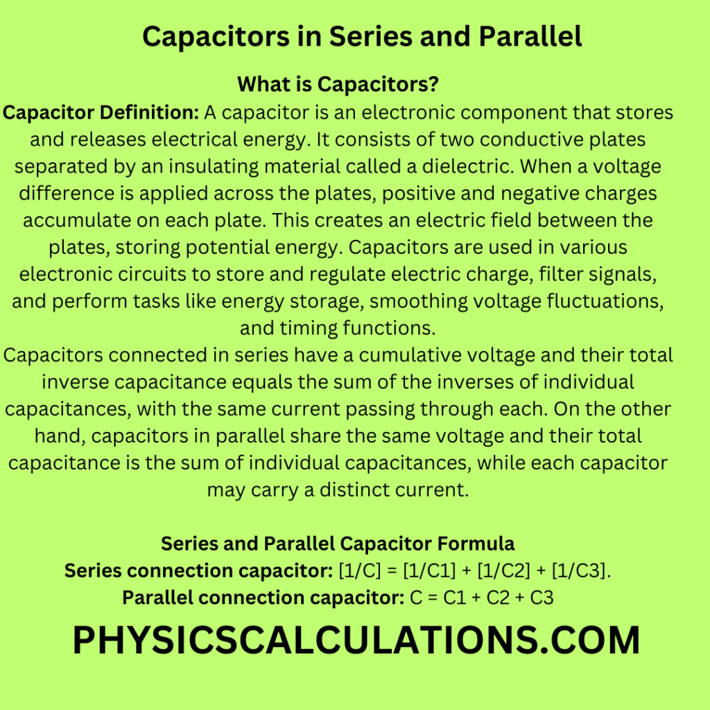
What is Capacitors?
Capacitor Definition: A capacitor is an electronic component that stores and releases electrical energy. It consists of two conductive plates separated by an insulating material called a dielectric. When a voltage difference is applied across the plates, positive and negative charges accumulate on each plate. This creates an electric field between the plates, storing potential energy. Capacitors are used in various electronic circuits to store and regulate electric charge, filter signals, and perform tasks like energy storage, smoothing voltage fluctuations, and timing functions. In this article, we will delve into the intricacies of capacitors in series and parallel, exploring their benefits, differences, and practical insights to help you harness their potential for enhancing your circuits.
Capacitors are essential components that store and release electrical energy, and arranging them in series or parallel can have a significant impact on circuit performance. The SI unit of capacitors is faradays.
Capacitors in Series and Parallel Explained
Capacitors connected in series have a cumulative voltage and their total inverse capacitance equals the sum of the inverses of individual capacitances, with the same current passing through each.
On the other hand, capacitors in parallel share the same voltage and their total capacitance is the sum of individual capacitances, while each capacitor may carry a distinct current.
Capacitors in Series
Capacitors in series involve connecting multiple capacitors end to end, so the positive terminal of one is connected to the negative terminal of the next. This arrangement increases the overall voltage rating while keeping the capacitance unchanged.
Therefore, the total capacitance in series-connected capacitors decreases inversely proportional to the number of capacitors. In other words, as you add more capacitors in series, the total capacitance decreases.
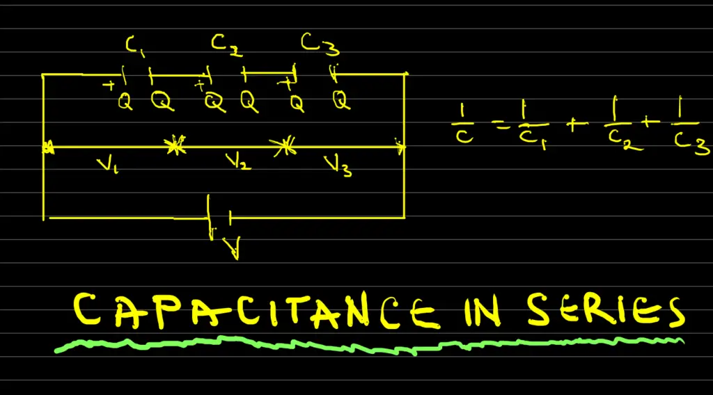
When we arrange capacitors in series as in the picture above, the following apply:
- The equivalent or combined capacitance (C) is: [1/C] = [1/C1] + [1/C2] + [1/C3].
Therefore, C = [C1C2] / [C1 + C2]
2. Capacitors C1, C2, and C3 all have the same charge Q
3. Total circuit voltage, V = V1 + V2 + V3 Where V1 = Q/C1, V2 = Q/C2, and V3 = Q/C3
Capacitors in Parallel
Conversely, capacitors in parallel are connected with their positive terminals together and their negative terminals together. This setup increases the overall capacitance while keeping the voltage rating constant. Additionally, when capacitors are connected in parallel, the total capacitance is the sum of the individual capacitances.
Thus, this configuration is useful when you need to increase the capacitance without altering the voltage handling capabilities.
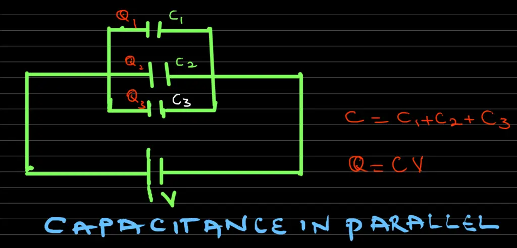
When capacitors are arranged in parallel as shown below, the following apply:
- The equivalent or combined capacitance C, is given by: C = C1 + C2 + C3
- C1, C2, and C3 are all the same potential difference V
- Total circuit charge, Q = Q1 + Q2 + Q3 Where Q1 = C1V, Q = C2V, and Q = C3V
Solved Problems: Capacitors in Series and Parallel
Here are a few solved problems on capacitors in series and parallel:
Problem 1: Parallel Capacitor
What is the equivalent capacitance of a 3μF capacitor and a 6μF capacitor connected in parallel?
Solution:
Equivalent capacitance, C = C1 + C2 = 3μF + 6μF = 9μF
Problem 2: Parallel Capacitor
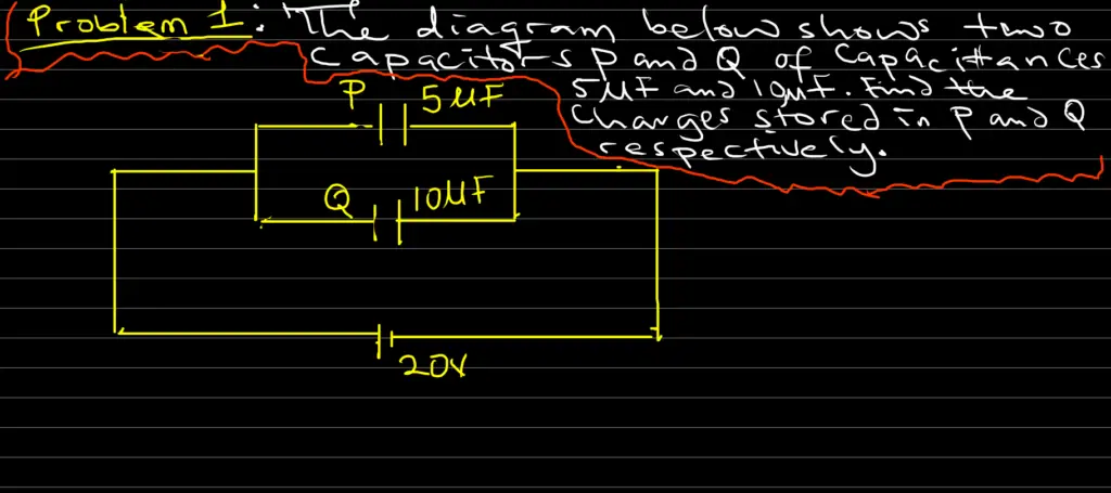
The diagram above shows two capacitors P and Q of capacitances 5μF and 10μF. Find the charges stored in P and Q respectively.
Solution
From C = Q/V, charge Q = CV
Qp = CpV = 5μF x 20 = 5 x 10-6 x 20 = 100 x 10-6 C = 100μC
Also, QQ = CQV = 10μF x 20 = 10 x 10-6 x 20 = 200 x 10-6 C = 200μC
Problem 3: Series Capacitor
Three capacitors each of capacitances 18μF are connected in series. Calculate the effective capacitance of the capacitors.
Solution
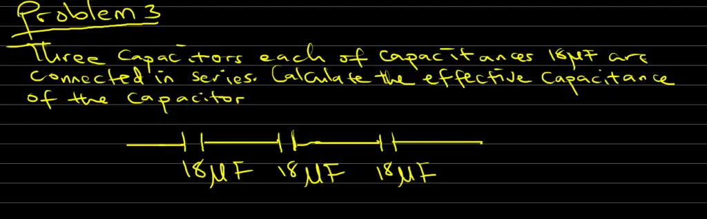
1/C = 1/18 + 1/18 + 1/18
Thus, 1/C = (1+1+1) / 18 = 3/18
We will now have 1/C = 3/18
Therefore, the capacitance, C = 18/3 = 6μF
Problem 4: Series Capacitor
The diagram below shows three capacitors C1, C2, and C3 of capacitance 2μF, 6μF and 3μF respectively. The potential differences across C1, C2, and C3 respectively are:
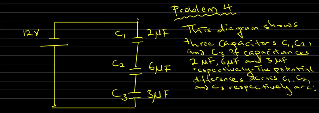
Solution
1/C = 1/C1 + 1/C2 + 1/C3 = 1/2 + 1/6 + 1/3 = (3+1+2) / 6 = 6/6 = 1
Thus, 1/C = 1
Therefore, C = 1
Now, the circuit charge Q = CV = 1 x 12 = 12C
From C = Q/V, the potential difference V = Q/C
Hence
V1 = Q/C1 = 12/2 = 6V;
Also V2 = Q/C2 = 12/6 = 2V,
While V3 = Q/C3 = 12/3 = 4V,
Therefore, the potential differences across C1, C2, and C3 are V1 = 6V, V2 = 2V, V3 = 4V
Problem 5: Series Capacitors
Two capacitances of 6μF and 8μF are connected in series. What additional capacitance must be connected in series with this combination to give a total of 3μF?
Solution
If C = total capacitance = 3μF, Cx = additional capacitance
1/C = 1/6 + 1/8 + 1/Cx
Thus, 1/3 = 1/6 + 1/8 + 1/Cx
Thus, 1/Cx = 1/3 – 1/6 – 1/8
1/Cx = (8-4-3) / 24 = 1/24
Therefore, Cx = 24μF
Problem 6: Combined Series and Parallel Connection
What is the resultant capacitance in the figure below
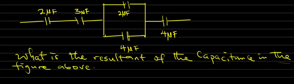
Solution
Capacitor 2μF, 3μF, and 4μF are in series with one another and also in series with a parallel combination of capacitors 2μF and 4μF.
1/C = 1/2 + 1/3 + 1/(2+4) + 1/4
Hence, 1/C = 1/2 + 1/3 + 1/6 + 1/4 = (6+4+2+3) / 12 = 15/12
Thus, 1/C = 15/12
Therefore, C = 12/15 = 0.8μF
Problem 7: Combined Series and Parallel Connection
What is the total capacitance in the circuit represented by the diagram below
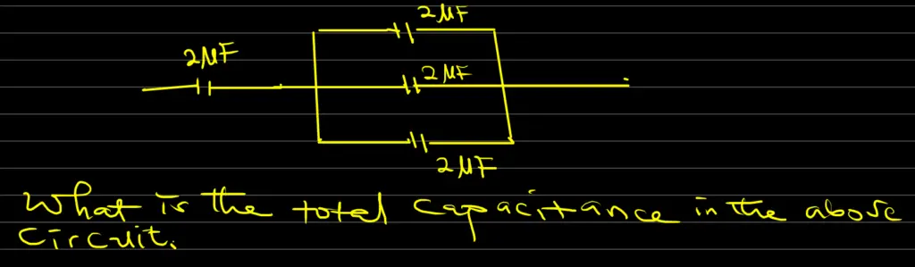
Solution
In parallel: 2μF + 2μF + 2μF = 6μF.
6μF in series with 2μF
Therefore, C = (6 x 2) / (6 + 2) = 12/8 = 1.5μF
Problem 8: Combined Series and Parallel Connection
The effective capacitance between points X and Y in the diagram below is 1.5μF. Find the value of the capacitance
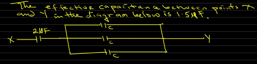
Solution
In parallel: C + C + C = 3C
Then 3C in series with 2μF
Total Capacitance, C = 1.5 = (2 x 3C) / (2 + 3C) = 6C / (2 + 3C)
Cross multiply 1.5 = 6C / (2 + 3C) to obtain
6C = 1.5(2 + 3C)
Thus, 6C = 3 + 4.5C
We will now have, 6C – 4.5C = 3
And 3 = 1.5C,
Therefore, C = 3/1.5 = 2μF
Therefore, the capacitance is 2μF
Benefits of Series and Parallel Capacitor Configurations
Series Configuration Benefits
- Voltage Sharing: Series-connected capacitors distribute the total voltage across each capacitor, ensuring balanced voltage sharing.
- Increased Voltage Rating: By combining capacitors in series, you can effectively achieve higher voltage ratings for your circuit.
- Voltage Division: Series capacitors facilitate voltage division, enabling different voltage drops across each capacitor.
Parallel Configuration Benefits
- Enhanced Capacitance: Parallel-connected capacitors provide increased overall capacitance, offering more charge storage.
- Improved Power Delivery: These configurations can supply higher currents when we need rapid power delivery.
- Fault Tolerance: If one capacitor fails in a parallel configuration, the others can continue to function.
Practical Insights for Implementation
Choosing Series or Parallel Configuration
Deciding between series and parallel capacitor configurations depends on the specific requirements of your circuit. If you need to maintain the same voltage rating while increasing capacitance, parallel connection is suitable. On the other hand, if you aim to boost voltage ratings without altering capacitance, series connection is the way to go.
Calculating Total Capacitance
For series-connected capacitors, calculate the reciprocal of the total capacitance by summing up the reciprocals of individual capacitances. In parallel, simply add up the capacitances for the total value. These calculations are essential for designing circuits with desired capacitance characteristics.
Dealing with Tolerances
Capacitors have tolerances that affect their actual values. In series, the tolerance of each capacitor compounds, possibly leading to a significant difference from the expected value. In parallel, however, the total capacitance is less affected by tolerances, providing more consistent results.
Practical Applications
Series and parallel configurations find applications in various electronic systems. Series capacitors are common in voltage multipliers, where the voltage needs to be stepped up. Therefore, we use parallel capacitors in power supply filtering to ensure stable voltage levels and minimize voltage ripples.
Parallel Capacitor vs Series Capacitor Table
Here is a comprehensive table comparing capacitors in parallel and series:
| Aspect | Capacitors in Series | Capacitors in Parallel |
|---|---|---|
| Voltage | Adds up (Voltage across each capacitor accumulates.) | Same (Voltage across each capacitor is identical.) |
| Total Capacitance | Inverse of total capacitance is the sum of inverses of individual capacitances. | Total capacitance is the sum of individual capacitances. |
| Current | Same current flows through all capacitors. | Different currents flow through each capacitor. |
| Energy Storage | Less effective energy storage compared to parallel configuration. | More effective energy storage due to higher total capacitance. |
| Effective Capacitance | Lower effective capacitance than the smallest individual capacitance. | Higher effective capacitance than the largest individual capacitance. |
| Safety | If one capacitor fails, it can disrupt the entire series circuit. | Failure of one capacitor does not severely impact the entire parallel circuit. |
| Applications | Used when voltage division is required, or for higher voltage tolerance. | Employed for increasing energy storage, filtering, and larger capacitance needs. |
| Equivalent Capacitance | Reciprocal of the sum of the reciprocals of individual capacitances. | Sum of individual capacitances. |
| Voltage Drop | Significant voltage drop across each capacitor. | Minimal voltage drop across each capacitor. |
| Calculation Complexity | More complex calculations due to inverse relationships. | Simplified calculations without inverses. |
This table provides a comprehensive overview of the differences between capacitors connected in parallel and series, aiding in understanding their behaviors and applications.
FAQs
Q: Can I mix capacitors of different capacitance values in a series configuration?
A: While it’s possible, it’s not recommended as it could lead to imbalanced voltage distribution and unpredictable results.
Q: What happens if one capacitor fails in a parallel configuration?
A: If one capacitor fails in a parallel setup, the others will continue to function, but the overall capacitance will decrease.
Q: How do I calculate the equivalent capacitance of capacitors in parallel?
A: Simply add up the capacitances of all the capacitors connected in parallel to get the total equivalent capacitance.
Q: Are there any disadvantages to using series-connected capacitors?
A: Yes, series configurations reduce the overall capacitance, which might not be ideal for applications requiring high capacitance.
Q: Can I combine series and parallel configurations in a single circuit?
A: Absolutely! Hybrid configurations can be used to achieve specific voltage and capacitance requirements.
Q: What’s the main advantage of using capacitors in parallel in audio systems?
A: Parallel capacitors can effectively filter out low-frequency noise, ensuring clean and high-quality audio output.
You may also like to read: